In-system calibration of a μA current sensor
One of my projects will be powered by a battery, and will sleep for long periods while it waits for user input. My battery life will depend on this sleep current, which might be about 10 µA. My handheld meter will measure this, but it suffers from mediocre common-mode rejection when I use it to measure high-side current. I really wanted to probe my sleep current and send it directly to an oscilloscope. These INA169 breakout boards seem like a convenient way to make this probe, but using them raises calibration, noise, and bandwidth questions. I want to describe how I put down a simple calibration circuit to give myself some confidence in this measurement.
Wiring the sensor
Figure 1 shows the current sensor, which is built around TI’s IN169 current sensor IC. Adafruit sells the breakout board I used, which builds in the IC, the current sensing resistor Rshunt, the current-to-voltage resistor Rload, and a bypass capacitor. It comes configured with a convenient gain of 1 V/A, and sells for about 10 USD. Sparkfun and others make similar breakout boards. These boards can be modified for different “burden voltages” and power configurations.
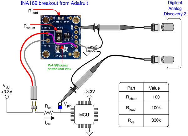
One of the modifications I make is to power the INA169 from the high side of my current measurement. This simplifies connecting the sensor, and there’s no advantage to increasing it above Vdd – the maximum output voltage is just below the Vin− input.
The second modification is to configure a gain of about 100 µA/V instead of 1 A/V. My quiescent currents will be between 1 µA and 100 µA, and I wanted less than 1 µA of noise with my Digilent oscilloscope. As shown in figure 1, I chose Rload to give me a voltage gain of 100, and Rshunt to give me about 300 µA full scale. This high voltage gain causes an offset voltage that can’t be neglected, which is why I built a calibration circuit into my prototype.
The calibration circuit is just a resistor, a header for the sensor, and a test point for the pin voltage. It’s not a lot of parts to add, and building the circuit right into my prototype gives me an easy way to make sure the sensor is still working correctly.
Calibration
Pulsing Vpin low captures the sensor’s slope and offset in one oscilloscope trigger. Figure 2 shows the raw sensor output during the pulse. The current source resistor, Rcs , sees Vdd − Ical Rshunt on one side, and Vpin on the other during the pulse. The current sensing resistor, Rshunt , is less than 1% of Rcs and I’ll neglect it. This gives a pulsed current of 3.3 V/330 kΩ = 10 µA. Looking at the ATmega328pb datasheet and making some measurements with a meter confirms this current.
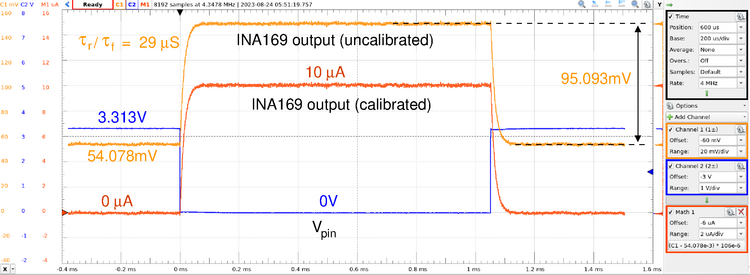
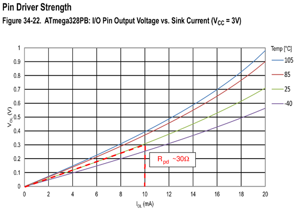
The ATmega328pb datasheet shows Vpin = Vdd for no output current, and I confirmed that with a meter. Figure 3 shows the ATmega328pb’s pulldown resistance when it sinks current. Vpin will be within 1 mV of 0 V when sinking 10 µA. My measured Vdd = 3.314 V, and my measured Rcs = 328.8 kΩ. This makes a calibration current of 10.1 µΩ. These numbers suggest that we can calibrate the sensor to about 1%, but I don’t want to push things past about 5%. Still, I’ll keep about three significant digits when I enter numbers into the Waveforms software for calibration.
The bottom right corner of figure 2 shows the calibration formula I used to make the calibrated data trace. I subtract off the 54.078 mV of offset, then I multiply the result by a slope of 10.1 µA/95.093 mV = 106 µA/V. The Waveforms software oscilloscope trace then shows a nicely calibrated sensor output.
Is it fast enough?
Figure 2 shows rise and fall times of about 29 µs for the sensor output. This gives a first-order bandwidth of 0.35/29 µs = 12 kHz. This is consistent with the INA169’s datasheet, which predicts a bandwidth of between 10 kHz and 20 kHz for a 100 kΩ gain resistor. This bandwidth is just fine for measuring my quiescent current when systems come in and out of sleep. I worry about missing high frequency spikes though, and I’ll make a low-side current measurement to confirm I’m not missing anything. It’s also not expensive to configure the sensor for something like 10 mA full scale, which would give you two orders of magnitude more bandwidth.