One of the pain points for new
Tcl users is the lack of an
obvious package repository and management system. Python has
pypi and
pip. Tcl has
Teapot and
Teacup, but these were more
popular when they were maintained by
ActiveState. If you just want to help users (or yourself) install a few Tcl packages hosted on Github, the Tin package manager is worth checking out.
I developed Testin as a way to get to know Tin. Once you manually install Tin, installing other packages is as easy as
$ sudo tclsh
% package require tin
% tin add -auto testin https://github.com/johnpeck/testin install.tcl
% tin install testin
...on linux (since the default package directory is owned by root).
If you're using Github for development anyway, Tin doesn't make you
understand a new package repository.
The Testin repository has detailed instructions for installing Tin,
Tcllib, and finally Testin.
A nugget: named arguments for Tcl procs in Testin
Testin has one function: intlist. It simply makes a list of integers, similar to Python's range. But it experiments with named arguments:
Nifty, right? The intlist function takes two arguments, but cmdline allows omitted arguments to have default values (in this case, the default first integer is 0). And named arguments make procedure calls easier to understand. This idea came from the Tcler's Wiki.
I've been trying to be better about throwing errors in my Tcl code for tcladu. There seem to be at least three ways to do this: error, throw, and return. Is there any difference? Here's what I tried:
# Demonstrate handling errors with Tcl

proc iterint {start points} {
    # Return a list of increasing integers starting with start with
    # length points
    set count 0
    set intlist [list]
    while {$count < $points} {
    lappend intlist [expr $start + $count]
    incr count
    }
    return $intlist
}

proc pdict {dict {pattern *}} {
   set longest 0
   dict for {key -} $dict {
      if {[string match $pattern $key]} {
         set longest [expr {max($longest, [string length $key])}]
      }
   }
   dict for {key value} [dict filter $dict key $pattern] {
      puts [format "%-${longest}s = %s" $key $value]
   }
}

proc throw_error { code } {
    switch $code {
    1 {
        set message "This error was thrown with error"
        set errorcode "FIRST_ERROR_CODE"
        error $message -errorcode $errorcode
    }
    2 {
        set message "This error was thrown with throw"
        set errorcode "SECOND_ERROR_CODE"
        throw $errorcode $message
    }
    3 {
        set message "This error was thrown with return -code error"
        set errorcode "THIRD_ERROR_CODE"
        return -code error -errorcode $errorcode $message
    }
    }
}

foreach code [iterint 1 3] {
    puts "-----------------------------------"
    try {
    throw_error $code
    } trap {FIRST_ERROR_CODE} {message optdict} {
    puts "Error handler for FIRST_ERROR_CODE"
    puts "Message is: $message"
    puts "Context:"
    pdict $optdict
    } trap {SECOND_ERROR_CODE} {message optdict} {
    puts "Error handler for SECOND_ERROR_CODE"
    puts "Message is: $message"
    puts "Context:"
    pdict $optdict
    } trap {} {message optdict} {
    puts "Catch-all error handler"
    puts "Message is: $message"
    puts "Context:"
    pdict $optdict
    }
}
puts "-----------------------------------"
...and here's the output:
-----------------------------------
Error handler for FIRST_ERROR_CODE
Message is: This error was thrown with error
Context:
-errorinfo  = -errorcode
    (procedure "throw_error" line 1)
    invoked from within
"throw_error $code"
    ("try" body line 2)
-errorcode  = FIRST_ERROR_CODE
-code       = 1
-level      = 0
-errorstack = INNER {invokeStk1 throw_error 1}
-errorline  = 2
-----------------------------------
Error handler for SECOND_ERROR_CODE
Message is: This error was thrown with throw
Context:
-errorcode  = SECOND_ERROR_CODE
-code       = 1
-level      = 0
-errorstack = INNER {returnImm {This error was thrown with throw} {-errorcode SECOND_ERROR_CODE}} CALL {throw_error 2}
-errorinfo  = This error was thrown with throw
    while executing
"throw $errorcode $message"
    (procedure "throw_error" line 11)
    invoked from within
"throw_error $code"
    ("try" body line 2)
-errorline  = 2
-----------------------------------
Catch-all error handler
Message is: This error was thrown with return -code error
Context:
-errorcode  = THIRD_ERROR_CODE
-code       = 1
-level      = 0
-errorstack = INNER {invokeStk1 throw_error 3}
-errorinfo  = This error was thrown with return -code error
    while executing
"throw_error $code"
    ("try" body line 2)
-errorline  = 2
-----------------------------------
The differences are in the error options dictionary captured by the try command. The errorstack key has a much larger value with the throw command. The various commands otherwise do the same thing.
The first thing I realized when I started to use
tcladu was the need for
convenience functions. For example, combinations of write_device
and read_device should be combined into a query command for
convenience. And it would be nice for those kind of commands to be in
the same tcladu package. So I started to write some Tcl, and I
realized I didn't really know how to manage the package version with
this high-level addition.
The tcladu.so binary already provides the tcladu namespace and
package version. I set this version in a makefile that also drives
testing, so I'd really like the makefile/binary package version to be
the source of truth. So I need to extract that package version in the
convenience code. It turns out that there's a
package command
for this. These links are to Tcl 9.0 documentation, but my usage doesn't
care.
Adding these lines
load ./tcladu.so
set version [package present tcladu]
package provide tcladu $version
...to the tcladu.tcl source file synchronizes the Tcl and binary
source versions. I can then package this up with
pkg_mkIndex -verbose . tcladu.so tcladu.tcl
...using the pkg_mkIndex command. This produces the pkgIndex.tcl script distributed with the package source files:
...where you can see the combination of sourcing and loading done to make the package available. These convenience functions are coming in tcladu version 1.1.0.
Removed references to Tcladu at Sourceforge and Gitlab.
Demonstration
Let's say you've downloaded a release binary from
Github, and you have a few (two)
ADU100s connected. You also need permissions to access the device,
but let's say you have those.
The package is just two files: pkgIndex.tcl, used by Tcl's
package procedure, and
tcladu.so, a binary produced from some c code.
Appended the package to Tcl's auto_path
The auto_path list tells Tcl where to look for packages.
Required the package
This both loads procedures into the tcladu namespace and initializes libusb.
Populated the connected device database
The discovered_devices command will populate a device database with
things like device handles and serial numbers. This must be called
before writing to or reading from devices.
Queried the device database for device 0
The serial_number command doesn't do anything with connected
hardware -- it just returns a serial number populated by
discovered_devices.
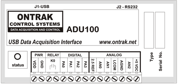
Sent the command to set/close the ADU100's relay
The write_device command takes a device index instead of some kind
of handle to identify the targeted device. It then takes an ASCII
command that you can find in the ADU100
manual to manipulate the
hardware relay. The last argument is a timeout for libusb (in
milliseconds), which will become more interesting when we get into
reading from the hardware.
Sent the command to read the relay status
Reading the relay status starts with telling the ADU100 to read the
status. It will prepare the result to be read by the next libusb
read. The return value for the RPK0 command is just a success code
-- not the relay status.
Read from the ADU100
The read_device command takes a device index, followed by the number
of bytes we want to read. This payload size is a placeholder for now,
although it has to be 8 bytes or larger. I want to keep it to handle
larger payloads on other Ontrak devices this might support in the
future.
The final argument is the familiar ms timeout. Libusb will throw a
timeout error if the read takes longer than this value. But this
error isn't fatal, and your code can catch this and simply try again.
This gives your application a chance to stay active while you wait for
a long hardware read.
The result is a Tcl list
containing the success code and return value. In this case, a 1
shows us that the relay is set/closed.
Sent the command to reset/open the ADU100's relay
This is the opposite of the set command.
Sent the command to check the relay status again
We'll now expect the hardware to report 0 for the relay status.
Read from the ADU100
The returned list is now 0 0, telling us that the command succeeded
and that the relay is reset/open.
One of my projects will be powered by a battery, and will sleep for
long periods while it waits for user input. My battery life will
depend on this sleep current, which might be about 10 µA. My handheld
meter will measure this, but it suffers from mediocre common-mode
rejection when I use it to measure high-side current. I really wanted
to probe my sleep current and send it directly to an
oscilloscope. These INA169 breakout boards seem like a convenient way
to make this probe, but using them raises calibration, noise, and
bandwidth questions. I want to describe how I put down a simple
calibration circuit to give myself some confidence in this
measurement.
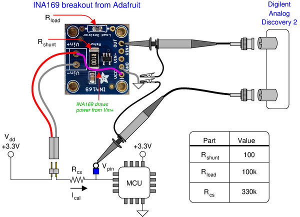
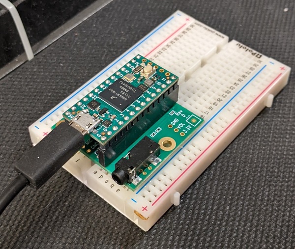
Wiring the sensor
Figure 1 shows the current sensor, which is built around TI’s IN169
current sensor IC. Adafruit sells the breakout board I used, which
builds in the IC, the current sensing resistor Rshunt, the
current-to-voltage resistor Rload, and a bypass
capacitor. It comes configured with a convenient gain of 1 V/A, and
sells for about 10 USD. Sparkfun and others make similar breakout
boards. These boards can be modified for different “burden voltages”
and power configurations.
Figure 1: Wiring the INA169 sensor and calibration circuit to measure 10 μA.
One of the modifications I make is to power the INA169 from the high
side of my current measurement. This simplifies connecting the
sensor, and there’s no advantage to increasing it above Vdd
– the maximum output voltage is just below the Vin− input.
The second modification is to configure a gain of about 100 µA/V
instead of 1 A/V. My quiescent currents will be between 1 µA and 100
µA, and I wanted less than 1 µA of noise with my Digilent
oscilloscope. As shown in figure 1, I chose Rload to give
me a voltage gain of 100, and Rshunt to give me about 300
µA full scale. This high voltage gain causes an offset voltage that
can’t be neglected, which is why I built a calibration circuit into my
prototype.
The calibration circuit is just a resistor, a header for the sensor,
and a test point for the pin voltage. It’s not a lot of parts to add,
and building the circuit right into my prototype gives me an easy way
to make sure the sensor is still working correctly.
Calibration
Pulsing Vpin low captures the sensor’s slope and offset in
one oscilloscope trigger. Figure 2 shows the raw sensor output during
the pulse. The current source resistor, Rcs , sees
Vdd − Ical Rshunt on one side, and
Vpin on the other during the pulse. The current sensing
resistor, Rshunt , is less than 1% of Rcs and
I’ll neglect it. This gives a pulsed current of 3.3 V/330 kΩ = 10
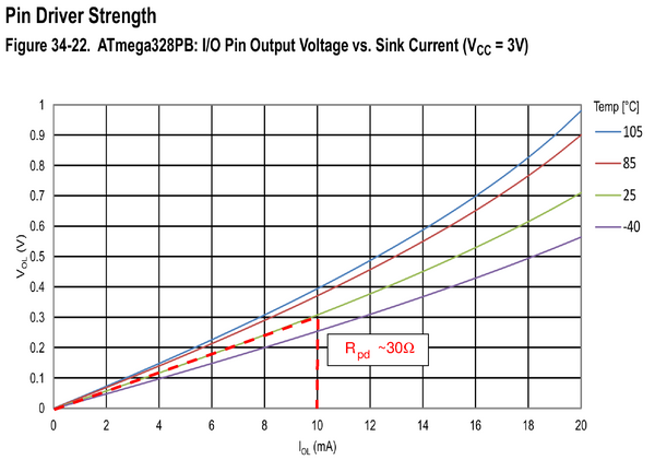
µA. Looking at the ATmega328pb datasheet and making some measurements
with a meter confirms this current.
Figure 2: Raw and calibrated sensor output.
The ATmega328pb datasheet shows Vpin = Vdd for
no output current, and I confirmed that with a meter. Figure 3 shows
the ATmega328pb’s pulldown resistance when it sinks
current. Vpin will be within 1 mV of 0 V when sinking 10
µA. My measured Vdd = 3.314 V, and my measured
Rcs = 328.8 kΩ. This makes a calibration current of 10.1
µΩ. These numbers suggest that we can calibrate the sensor to about
1%, but I don’t want to push things past about 5%. Still, I’ll keep
about three significant digits when I enter numbers into the Waveforms
software for calibration.
Figure 3: ATmega328pb pin pulldown strength at Vdd = 3V.
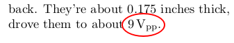
The bottom right corner of figure 2 shows the calibration formula I
used to make the calibrated data trace. I subtract off the 54.078 mV
of offset, then I multiply the result by a slope of 10.1 µA/95.093 mV
= 106 µA/V. The Waveforms software oscilloscope trace then shows a
nicely calibrated sensor output.
Is it fast enough?
Figure 2 shows rise and fall times of about 29 µs for the sensor
output. This gives a first-order bandwidth of
0.35/29 µs = 12 kHz. This is consistent with the INA169’s datasheet,
which predicts a bandwidth of between 10 kHz and 20 kHz for a 100 kΩ
gain resistor. This bandwidth is just fine for measuring my quiescent
current when systems come in and out of sleep. I worry about missing
high frequency spikes though, and I’ll make a low-side current
measurement to confirm I’m not missing anything. It’s also not
expensive to configure the sensor for something like 10 mA full scale,
which would give you two orders of magnitude more bandwidth.
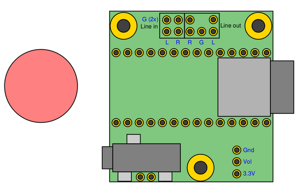
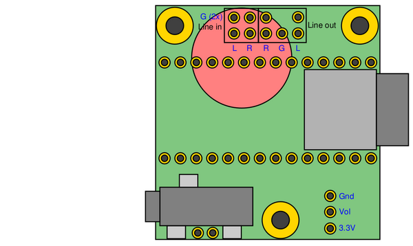
Xfig's depth settings can create some headaches when you use figure libraries. Library figures can use depths that conflict with your current drawing. Say I have this drawing of the Teensy Audio Board and a red circle,
...and then I move the red circle over the board:
This is clearly not what I want. The circle has a depth of 50, and
the board has depths between 10 and 60. The circle ends up on top of
some objects and not others. If you were using PowerPoint, you would
just select Bring to Front or Send to Back to arrange the objects.
But Xfig requires setting the depth of each member object
individually, which you should really do with a script like
figdepth.
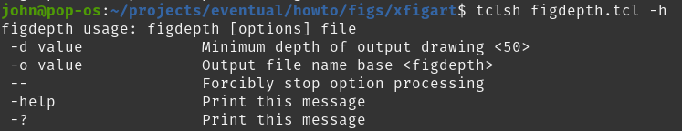
Using figdepth
Figdepth has some options, the most important of which is the minimum depth argument
...which sets the depth of the topmost object in a fig file. The
script simply increments all depths by some number to make this
minimum depth to be your setting. You will, of course, need to have
everything you want to modify in its own fig file. You can then run figdepth like
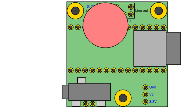
...to write your new depth-adjusted figure. Use Xfig's
merge command to
bring the new figure into your old drawing. My new drawing looks like this:
...with all objects in the Teensy Audio Board at a deeper depth than
the red circle.
How does it work?
The Fig file format is
really simple, which is one reason why I like Xfig so much. You can
figure out what kind of object each line describes by looking at the
first character. You then figure out which number in the line is the
object's depth and increment it. The switch statement below shows how
one line is processed.
proc increase_object_depth { xfig_line depth_increase} {
    # Return a new xfig line with the depth increased
    #
    # Arguments:
    #   xfig_line -- Single line from an xfig file
    #   depth_increase -- Amount to increase the depth
    set entry_list [split $xfig_line]
    set first_character [lindex $entry_list 0]
    switch $first_character {
    "0" {
        # Color object -- nothing to do
        return $xfig_line
    }
    "1" {
        # Ellipse
        set depth_index 6
        set old_depth [get_object_depth $xfig_line]
        set new_depth [expr $old_depth + $depth_increase]
        set new_entry_list [lset entry_list $depth_index $new_depth]
        set new_line [join $new_entry_list]
        return $new_line
    }
    "2" {
        # Polyline (also imported picture bounding boxes)
        set depth_index 6
        set old_depth [get_object_depth $xfig_line]
        set new_depth [expr $old_depth + $depth_increase]
        set new_entry_list [lset entry_list $depth_index $new_depth]
        set new_line [join $new_entry_list]
        return $new_line
    }
    "3" {
        # Spline
        set depth_index 6
        set old_depth [get_object_depth $xfig_line]
        set new_depth [expr $old_depth + $depth_increase]
        set new_entry_list [lset entry_list $depth_index $new_depth]
        set new_line [join $new_entry_list]
        return $new_line
    }
    "4" {
        # Text
        set depth_index 3
        set old_depth [get_object_depth $xfig_line]
        set new_depth [expr $old_depth + $depth_increase]
        set new_entry_list [lset entry_list $depth_index $new_depth]
        set new_line [join $new_entry_list]
        return $new_line
    }
    "5" {
        # Arc
        set depth_index 6
        set old_depth [get_object_depth $xfig_line]
        set new_depth [expr $old_depth + $depth_increase]
        set new_entry_list [lset entry_list $depth_index $new_depth]
        set new_line [join $new_entry_list]
        return $new_line
    }
    "6" {
        # Compound -- nothing to do
        return $xfig_line
    }
    default {
        # Some non-object -- nothing to do
        return $xfig_line
    }
  }
}
Having trouble with cmdline?
Figdepth
uses the
cmdline
package from
tcllib
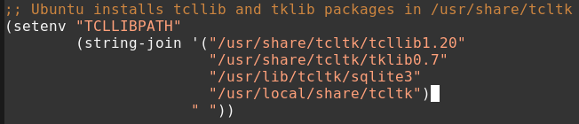
to handle command line arguments. I usually run scripts out of Eshell in Emacs, so I have this in my .emacs:
...to set the TCLLIBPATH environment variable. This tells Tcl where to find Tcllib's packages.
I still love Xfig when I need
to make a sketch of something with roughly-correct diminsions. I've
been neglecting my
Xfigart
repository, but I'm going to try to be better. I'll start with this
drawing of the
CES-571423-28PM
speaker from CUI.
The siunitx package for LaTeX
makes it easy to handle units in both normal and math modes. I end up needing units like Vrms when talking about electronics, so I add this in my preamble:
I've been wanting to experiment with audio signal processing on the
Teensy, so I bought a Teensy 4.0 and an
Audio Adaptor Board.
I had to do a bit of research to find the right headers to plug one
board into the other. I ended up with the headers listed below.
I've been interested in
fieldbusses lately, and
MODBUS in particular is used
by some pretty cheap hardware modules. It also offers "driverless"
communication — you don't need a .dll or .so file to talk to your
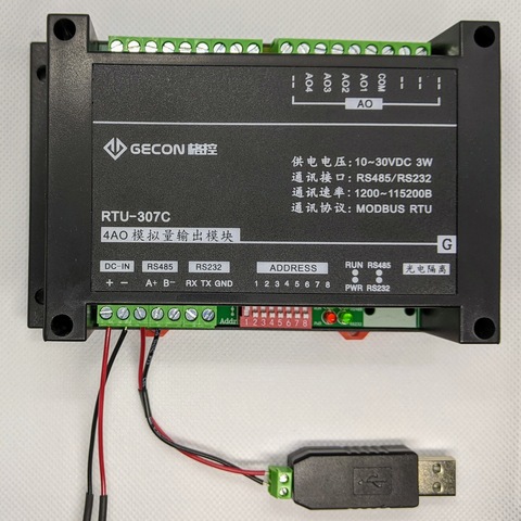
hardware. The hardware I've been experiementing with is shown below:
...and can be bought from eBay for around 50 USD. I found some very
useful code on
the Tcl wiki
and was able to write and read from registers with a USB/RS-485
adaptor. The RTU-307C user's manual
implies that you can change the RS-485 baud from 9600, but I wasn't
able to figure out how that works.
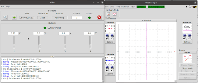
After some more help from
The Tcler's Wiki, I put
together a GUI to demonstrate MODBUS communication with the RTU-307C
module. The animation below shows the GUI next to an oscilloscope
(yelloscope) display.
The wiki helped me get the mouse wheel to move those sliders.